HMS SENSOR ARRANGEMENT MATTERS
HMS SENSOR ARRANGEMENT MATTERS
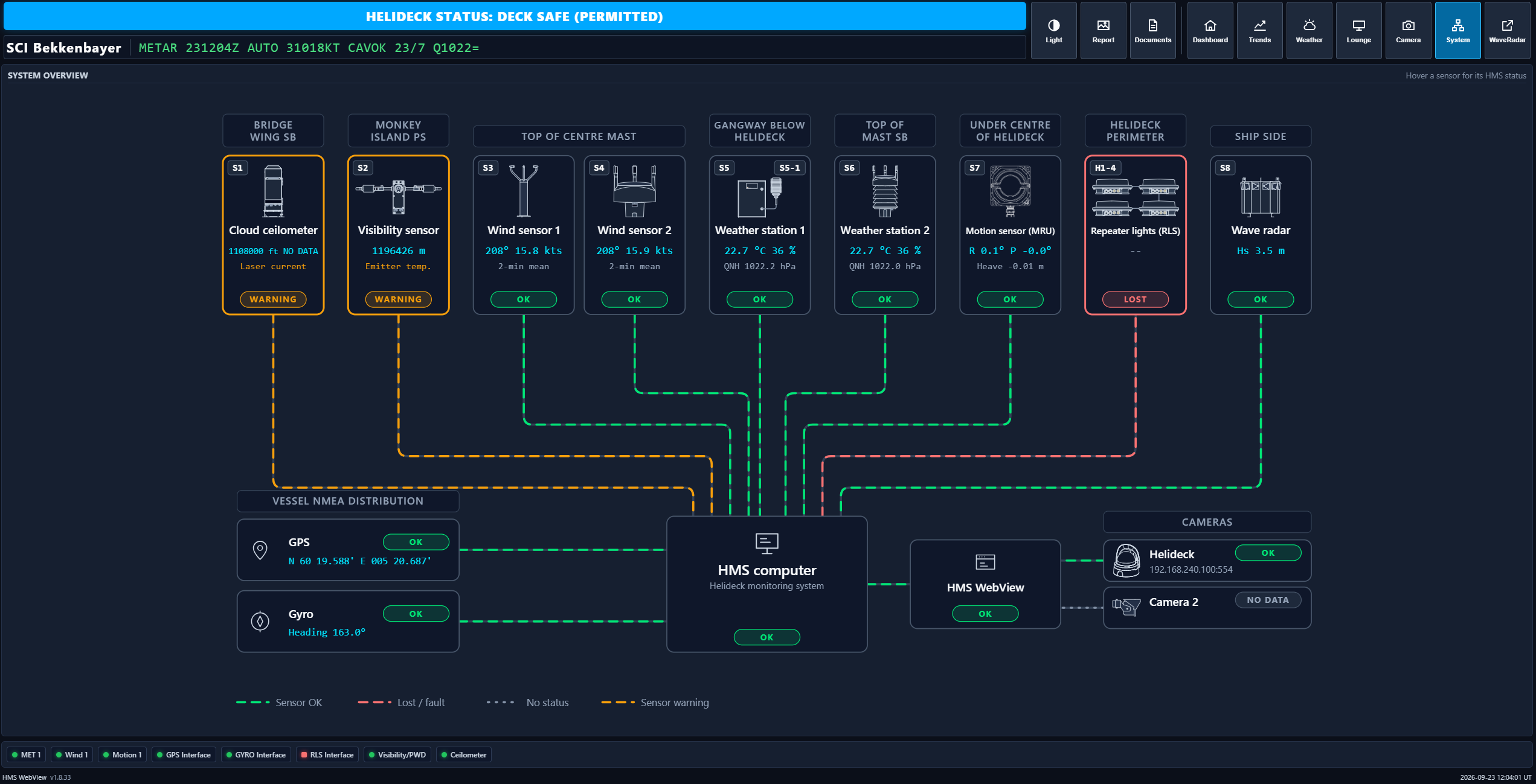
When operators discuss helideck compliance, attention is often focused on software, displays, reports and sensors calibration certificates. Yet some of the most significant challenges arise long before a Helideck Monitoring System (HMS) is commissioned.
The quality of any HMS depends on the quality of the data it receives. Incorrectly type and positioned wind sensors, motion reference units (MRUs) and meteorological sensors can introduce measurement errors that severely compromise both operational decision-making and regulatory compliance.
For offshore vessels and installations, planning the sensor arrangement is therefore one of the most critical phases of any HMS project.
COMPLIANCE STARTS WITH DATA QUALITY
CAP 437 Edition 9, HMS Standard Rev 9c and other modern helideck regulations place increasing emphasis on reliable and accurate operational data. While software, displays and reporting tools remain important, compliance ultimately depends on the quality of the measurements entering the system. Well-positioned sensors provide confidence for helicopter crews, helideck operators and vessel owners. Poorly positioned sensors or selecting the wrong environmental specification can undermine even the most advanced monitoring system.
For offshore operators planning new installations, upgrades or fleet-wide compliance projects, sensor placement should never be viewed as a minor detail. It is one of the most important factors in achieving both safe operations and long-term compliance.
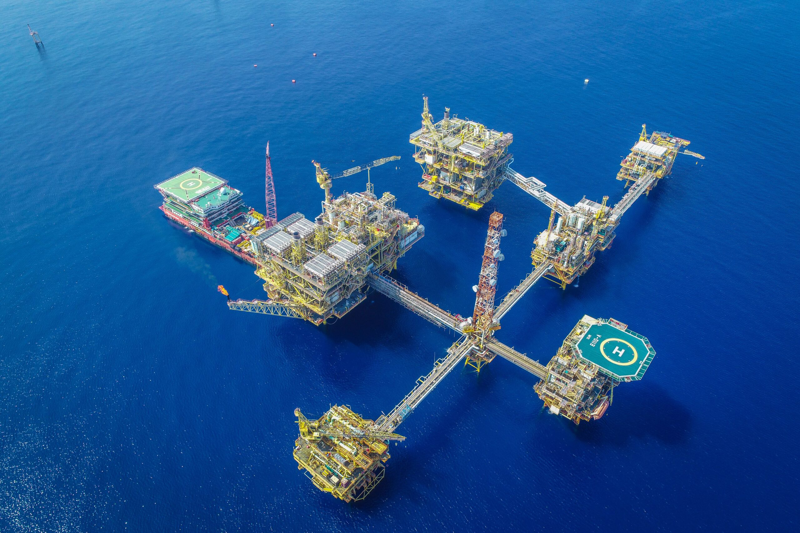
NO TWO OFFSHORE ASSETS ARE THE SAME
Unlike aircraft or vehicles built in large production series, offshore vessels and installations often have unique layouts. Helidecks may be located above accommodation blocks, near funnels, beside cranes, on cantilever structures or close to other equipment that influences airflow and vessel motion.
As a result, there is rarely a single sensor arrangement that works for every asset. An installation that performs well on one vessel may produce unacceptable measurement errors on another vessel with a different deck arrangement, hull form or topside configuration.
MRU MOUNTING ARRANGEMENT
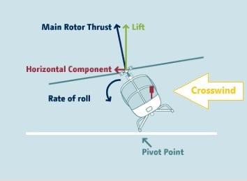
The primary purpose of the HMS/MRU is to provide the pilot and deck crew with real-time, predictive data to prevent dynamic rollovers or deck-sliding accidents before they occur.
Consequently, the helicopter’s Centre of Gravity (CG) is the critical point of measurement. Located directly below the main rotor mast in the cabin ceiling, the CG sits approximately 2 meters above the helideck level. Because an MRU cannot be physically mounted at this exact point, the system must precisely calculate and measure the vertical, longitudinal, and lateral accelerations experienced by the helicopter, in addition to roll, pitch, and inclination.
To accurately capture representative motions experienced by helicopter itself the MRU should for this reason be located as close as possible to the centre H of the helideck. Mounting a Rev. 9c HMS MRU remotely and away from the helideck support structure should be avoided unless absolutely necessary.
HMS Standard Helideck Monitoring Systems Rev. 9c (Section 4.1, Note 2) defines a strict hierarchy for MRU placement, prioritizing direct helideck-structure integration over remote calculations.
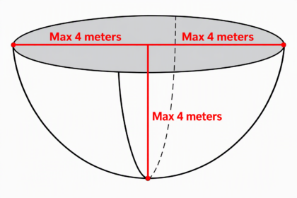
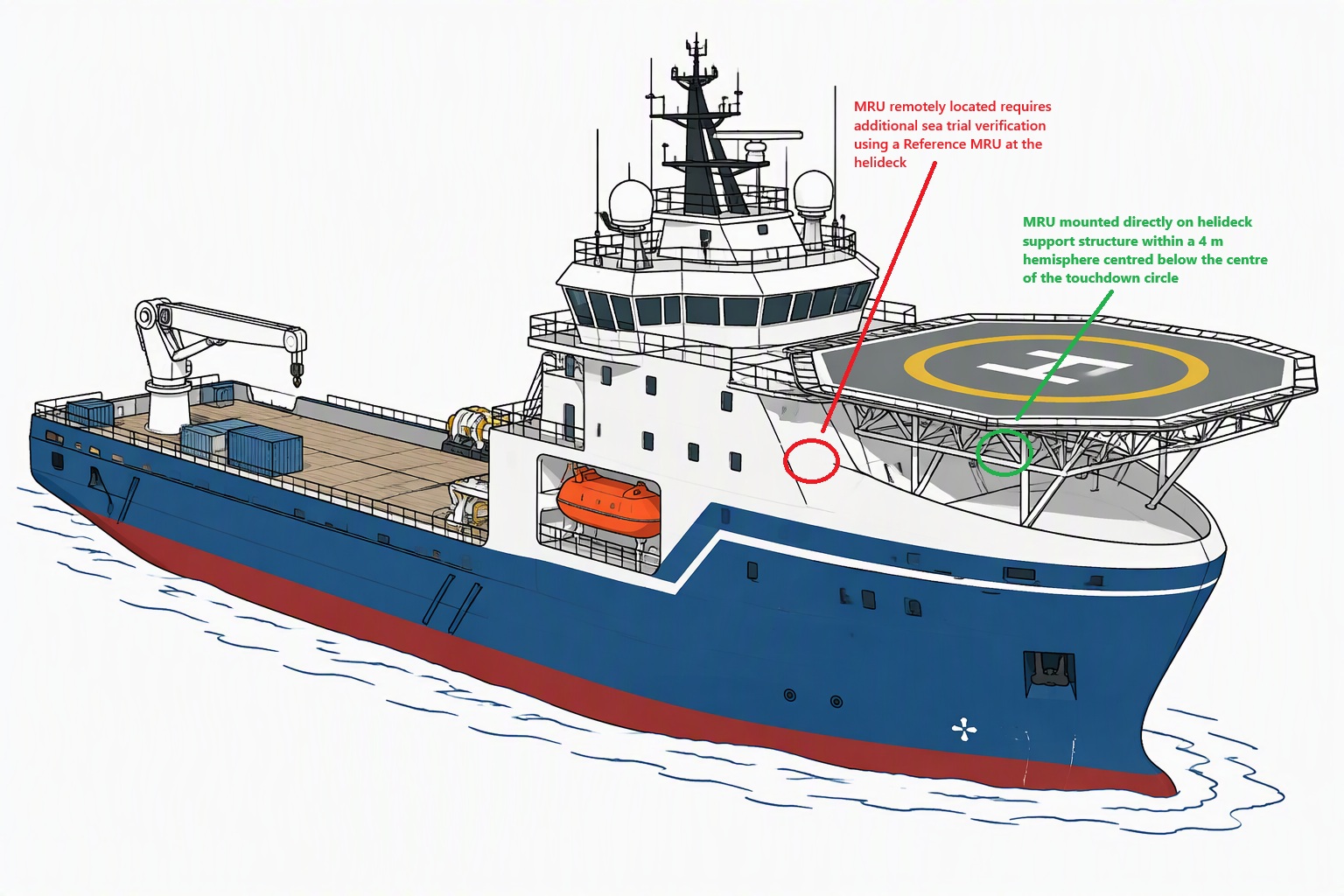
Where the primary MRU location (4.1 Note 2 a) is not practicable, Rev. 9c permits three alternative arrangements:
| Mounting Option | Location Criteria | Operational & Compliance Impact |
| Primary Location (4.1 Note 2 a) | Directly below the “H” marking. Mounted on the helideck support structure within a 4-meter radius hemisphere beneath the center of the Touchdown/Positioning Marking (TDPM) circle. | The Industry Gold Standard. Deliveries are highly predictable, cost-effective, and ensure seamless validation during Sea Acceptance Testing (SAT). No lever-arm compensation is required. |
| Alternative 1 (4.1 Note 2 b, dot 2) | Conservative Helideck Structure Location. Clamped to the helideck support structure, forward of the TDPM centerline, and within 3 meters below the deck level. | The Preferred Backup. Introduced for assets lacking physical access directly beneath the center of “H”. Lever-arm corrections are not required. While it experiences slightly higher localized accelerations, potentially reducing uptime margins marginally, commissioning remains simple and fully compliant with Section 4.1 accuracy limits. |
| Alternative 2 (4.1 Note 2 b, dot 1) | Optimistic Helideck Structure Location. Mounted further aft on the helideck support structure, but remaining within the white helideck perimeter line. | High Administrative Burden. This location experiences fewer physical motions but forces the use of complex lever-arm corrections. This drastically increases the commissioning effort, requiring exhaustive documentation in the Data Validation Report (DVR) and the UK-CAA/HCA SAT. It extends commissioning timelines by several days and introduces a long-term risk of data loss if settings are corrupted. |
| Alternative 3 (4.1 Note 2 b) | Remote Vessel Structure Location. The MRU is moved entirely away from the helideck structure and placed within the primary hull or superstructure. | Critical Risk & Financial Penalty. Requires a remote reference MRU on the helideck surface during a mandatory offshore Sea Trial. Measures do not naturally reflect helideck motions, demanding highly precise sensor hardware and advanced lever-arm software algorithms to compensate. |
THE REALITY OF REMOTE MRU INSTALLATIONS (ALTERNATIVE 3)
ShoreConnection’s extensive track record includes 200+ successfully delivered HMS 900 9c systems, all utilizing either the Primary or Alternative 1 mounting configurations. Our field experience with Alternative 2 and Alternative 3 positions has proven that remote mounting should be strictly avoided due to severe operational and financial penalties:
- The Sea Trial Mandate: To validate a remote MRU under Alternative 3, a sea trial must be conducted in rough sea states approaching the vessel’s Pitch, Roll, and Heave (PRH) limits. The remote sensor’s data must be compared against a temporary reference MRU temporarily mounted on the surface of the helideck at the center of the yellow TDPM circle.
- The 2-Year Recurring Cost: This validation is not a one-time expense. It must be repeated every two years for the biennial Data Validation Report (DVR) renewal, creating a massive, recurring financial burden for specialized equipment and offshore personnel.
- Operational Grounding: Temporary electrical installations and loose cabling across the deck are strictly prohibited by Class and IEC regulations. Furthermore, placing a temporary reference MRU at the centre of the helideck completely halts all flight operations for the duration of the sea trial.
- High Risk of Failure: Because helideck structures may move independently from the primary vessel hull, there is a very high probability that a remote MRU will fail to meet the strict correlation tolerances during sea trial validation.
Conclusion: What initially appears to be a convenient or space-saving location within the vessel hull ultimately results in an expensive, complex, and recurring compliance burden. Addressing the MRU mounting arrangement early in the vessel and helideck design phase is essential to eliminate these technical challenges and financial risks.
THE CHALLENGE OF WIND MEASUREMENTS
Wind is arguably the most important environmental parameter displayed to helicopter crews. However, obtaining representative wind measurements offshore is not always straightforward.
Wind sensors mounted too close to structural obstructions are highly susceptible to turbulence, shielding effects or accelerated airflow. Primary sources of interference include:
- Funnels and exhaust plumes
- Accomodation blocks and hull superstructures
- Vertical towers, derricks or jack-up legs
- Erected deck cargo
- Obstacles such as antennas or masts
- The landed helicopter itself during on-deck operations
This exposure can result in wind speed and direction readings that differ significantly from the actual conditions reported in the Helideck Pre-Flight Weather Report. More critically, this may result in an underestimation of the actual crosswind (Relative Wind Direction/Speed) experienced by the helicopter while it is “hot on deck” with the rotor at idle. This could compromise the vital on-deck RWD (crosswind) monitoring function introduced in Rev. 9c, which is intended to help prevent Dynamic Rollover (capsizing) and deck-sliding incidents caused by strong crosswinds.
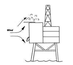
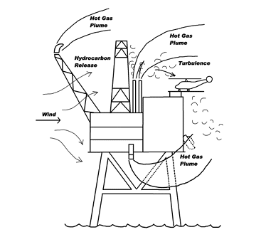
In some cases, two wind sensors positioned in different locations is required to ensure reliable undisturbed wind flow in 360 degrees wind compass under varying wind conditions. ShoreConnection has successfully implemented such alternative sensor arrangements on numerous offshore vessels and fixed platforms, utilizing two wind sensors in combination with our seamless automatic wind-voting system. This system automatically selects between wind-restricted sectors (WRS), effectively overcoming these operational challenges.
Other installations may require a Wind LIDAR, the only technology capable of delivering full 360‑degree compass coverage in some cases, and ShoreConnection provides 4 Hz Wind 200 and 350 m LIDAR units to meet this need.
MRU/WIND SENSORS ENVIRONMENTAL REQUIREMENTS
Selected MRU and wind sensors must be fully compatible with their intended operating environment.
For instance, certain MRUs designed for indoor installation have a limited operating range of 0°C to +55°C. Consequently, they are entirely unsuitable for helideck support structure mounting, where temperatures can drop below 0°C in winter and reach up to +70°C on a sunny day. Similarly, unheated wind sensors are inadequate for cold climates prone to icing and snowfall.
All such environmental limitations must be identified and systematically accounted for during the design phase.
RETROFITS PRESENT UNIQUE CHALLENGES
More than half of helideck monitoring projects involve upgrading or replacing existing systems rather than equipping newbuild vessels. In retrofit projects, the original sensor locations may not have been selected according to current requirements or best practices.
Operators must therefore strike a delicate balance between:
- Achieving optimum sensor positioning
- Minimising installation costs
- Reusing existing cable routes
- Reducing vessel downtime
A successful retrofit often requires engineering compromises to safeguard measurement quality and ensure full regulatory compliance.
WHY EARLY ENGINEERING SAVES TIME AND MONEY
One of the most common causes of project delays is discovering sensor placement conflicts after equipment has already been ordered or installed. Conducting a detailed review during the sales engineering and planning phase allows potential challenges to be identified and mitigated early.
By addressing structural constraints, signal blockages, and environmental limitations prior to procurement, operators can eliminate the need for costly field modifications, prevent extended vessel downtime, and guarantee a smooth, predictable path to compliance. Investing in thorough front-end engineering is not an added project expense—it is the single most effective way to protect the project timeline and budget.
EXPERIENCE YOU CAN RELY ON
Every vessel and helideck installation comes with its own constraints, which is why sensor placement should be considered as part of the overall system design rather than in isolation. ShoreConnection’s long experience with helideck monitoring systems allows us to advise customers early in the process and engineer solutions that take account of regulatory requirements, vessel design, installation constraints and lifecycle cost. The goal is simple: to find the right solution from the start and avoid unnecessary modifications, validation work and cost later.